
DESCRIPTION:The variable Area Flow meter is an instrument for measuring the flow of liquids or gases in pipelines. It includes a vertical tube through which the fluid flows whose diameter increases from the bottom to the top and a float which can move v
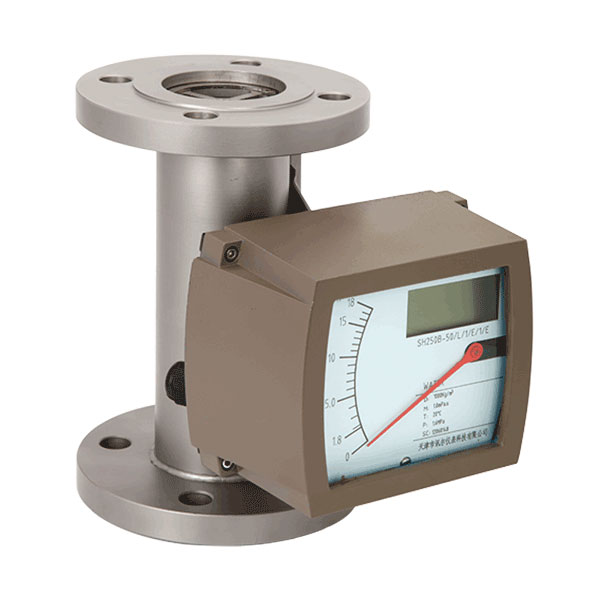
The variable Area Flow meter is an instrument for measuring the flow of liquids or gases in pipelines. It includes a vertical tube through which the fluid flows whose diameter increases from the bottom to the top and a float which can move vertically in the tube. As the flow increases this float moves to a higher position until its resistance to the fluid flow is balanced by th?float's buoyed weight in the fluid, a value which is constant and independent of the flow rate. The position of the iloat is a measure of the flow rale. The flow rate values can be read on a scale.
-Mechanical display and LCD display
-Robust and universal
-The short-stroke design allows the measurement of high flow rate using a relative short metering tube
-Special application is for hazardous, dangerous or aggressive fluid, for high temperature and high pressure rates
-All stainless steel design provides a safe measurement of a variety of liquids, gases and sleam- The measuring section can be equipped with a heating jacket
-Standard rotameter is mounted in a vertical pipeline with flow direction upwards
|
Application Range |
(1)Gas;(2)Liquid;(3)Steam |
|
Turndown Ratio |
10:1 |
|
Accuracy(Refer to the accuracy on the nameplate) |
±1.0% & ±1.5% &± 2.5% |
|
Temperature |
|
|
Max. Process Temperature |
T1 level:150℃ |
|
T2 level:300℃ |
|
|
T3 level:350℃ |
|
|
Pressure |
|
|
Nominal Operating Pressure |
DN15{aspcms:sitetitle}.DN50:4.0Mpa |
|
DN65{aspcms:sitetitle}.DN200:1.6Mpa |
|
|
Max. Pressure Rating |
DN15:32Mpa; DN25:25Mpa;DN50:20Mpa |
|
DN80:10Mpa;DN100:6.4Mpa |
|
|
DN125{aspcms:sitetitle}.DN150:4.0Mpa |
|
|
Model |
SH250 |
Description |
|||||||||
|
Diameter |
XXX |
|
|
|
|
|
|
|
|
|
015: DN15 100: DN100 200: DN200 |
|
Power Supply |
N |
|
|
|
|
|
|
|
|
Mechanical Display; No output |
|
|
A1 |
|
|
|
|
|
|
|
|
Mechanical Display; 0-1000Hz Output |
||
|
A2 |
|
|
|
|
|
|
|
|
Mechanical Display; 4-20mA Output; 24V DC |
||
|
B |
|
|
|
|
|
|
|
|
LCD Display; No Output; Battery |
||
|
C |
|
|
|
|
|
|
|
|
LCD Display; Pulse Output; 24V DC |
||
|
D |
|
|
|
|
|
|
|
|
LCD Display; 4-20mA + Pulse Output; 24V DC power supply |
||
|
Notice |
|
|
|
|
|
|
|
|
RS485 and Hart are optional for C and D converter |
||
|
Reset Function |
Y |
|
|
|
|
|
|
|
Yes |
||
|
N |
|
|
|
|
|
|
|
No |
|||
|
Flow Range |
XX |
|
|
|
|
|
|
Refer to the Range Table |
|||
|
Fluid |
L |
|
|
|
|
|
Liquid |
||||
|
G |
|
|
|
|
|
Gas |
|||||
|
Material |
S4 |
|
|
|
|
Body and Float: SS304 |
|||||
|
S6 |
|
|
|
|
Body and Float: SS316 |
||||||
|
SF |
|
|
|
|
Body: SS304; Float: PTFE |
||||||
|
XX |
|
|
|
|
On request |
||||||
|
Installation Way |
H |
|
|
|
Horizontal Installation |
||||||
|
V |
|
|
|
Vertical Installation |
|||||||
|
Structure |
1 |
|
|
Standard Structure |
|||||||
|
2 |
|
|
Heat Insulation |
||||||||
|
3 |
|
|
Damper for gas measurement |
||||||||
|
4 |
|
|
High Temperature |
||||||||
|
5 |
|
|
High Pressure |
||||||||
|
Explosion Proof |
NA |
|
Safety Field without Ex-Proof |
||||||||
|
BT |
|
Exd II BT4 |
|||||||||
|
CT |
|
Exib II CT4 |
|||||||||
|
Connection |
DXX |
D16: DIN PN16 flange; D25: DIN PN25 … |
|||||||||
|
AXX |
A15: ANSI 150# flange; A30: ANSI 300#… |
||||||||||
|
JXX |
J10: JIS 10K flange; J20: JIS 20K … |
||||||||||